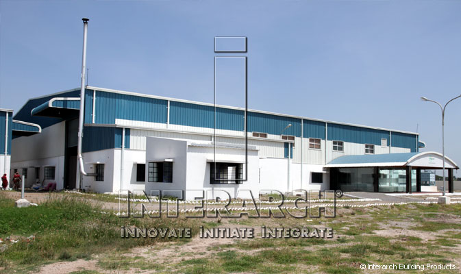
Interarch pre-engineered buildings are custom-designed to meet your exact requirements. The basic parameters that define a pre-engineered building are:
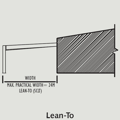
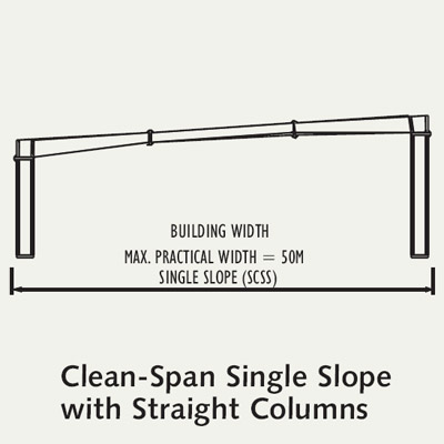
Building width is defined as the distance between the outer side of an eave strut of one side wall to the outer side of an eave strut of the opposite side wall.
This is defined as the distance between the outside flanges of endwall columns in the opposite endwalls, and is a combination of several bay lengths.
End bay length is the distance from the outer side of the outer flange of endwall columns to centre line of the first interior frame column.
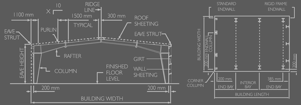
This is the distance between the centre line of two adjacent interior mainframe columns. The most common bay spacings are 6 mts, 7.5 mts and 9 mts. The bay lengths can go up to 15 mts.
Building height is the eave height, which is usually the distance from the bottom of the mainframe column base plate to the top outer point of the eave strut. Eave height can go up to 30 mts. When columns are recessed or elevated from finished floor, eave height is the distance from finished floor to the top of the eave strut.
This is the angle of the roof with respect to the horizontal base. The most common roof slope is 1/10. However, any practical roof slope is possible.
Unless otherwise specified, Interarch pre-engineered buildings are designed for the following minimum loads:
Design for seismic loads, collateral loads or any other local conditions must be specified at the time of quotation.
Loads are applied in accordance with the latest American Codes and Standards applicable to pre-engineered buildings unless otherwise requested at the time of quotation.
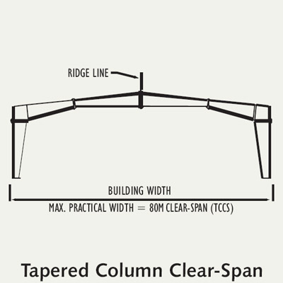
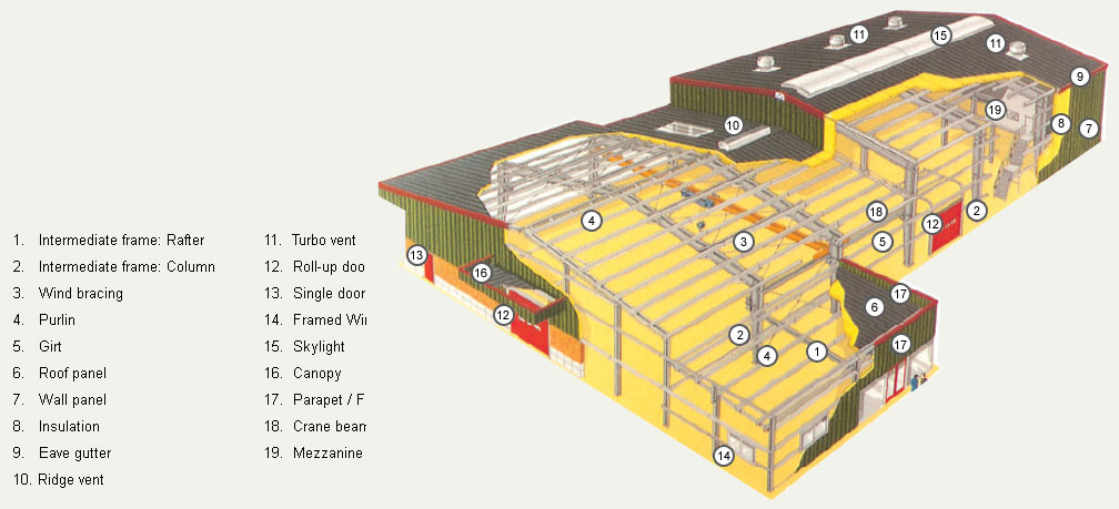
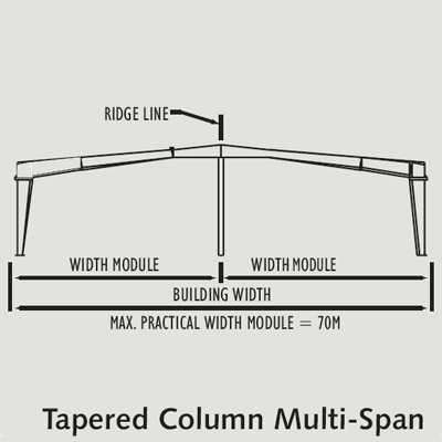
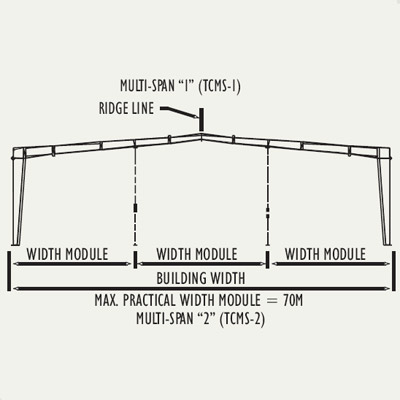
Interarch buildings are optimised to meet specific requirements of each client. Commonly
used primary framing systems are shown below. All frames shown are symmetrical about the ridge line. Framing systems asymmetrical about the ridge line, multi-span systems with unequal width modules and frames outside the ranges shown are possible, but require
special study.
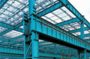
Primary framing is manufactured such that only bolted connections are required.
Intermediate frames consist of built-up welded members. For multi-span frames,
intermediate columns are either pipe sections, hot-rolled profiles or built-up welded profiles. Frames are complemented by flange bracing, connection bolts and anchor bolts. Column bases are usually pinned. Fixed connections, if required as per design, can also be provided.
Endwall frames consist of either built-up welded, hot-rolled or cold-rolled columns which support a cold-formed or hot-rolled rafter. Frames are complemented by connection bolts, anchor bolts and wind bracing, if required.
Wind bracing provides longitudinal stability for the building. It consists of cross-bracing
located in the roof and side walls in one or more bays depending on the quantity of load
and the length of the building. When required, cross-bracings can be replaced by wind
portal frames or by fixed base wind columns located adjacent and connected to the
mainframe columns.
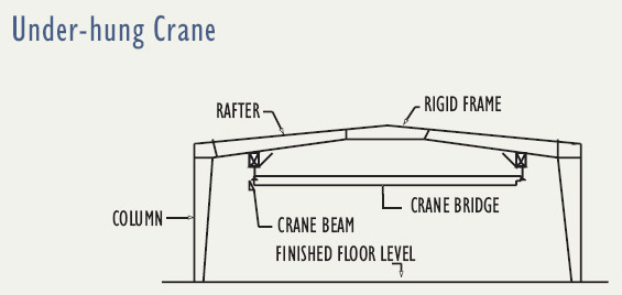
Crane brackets support the crane beams and are fixed to the column flanges.
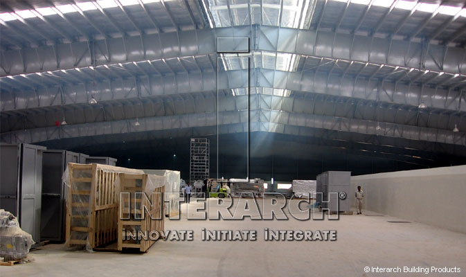
Secondary framing consists of elements which support the roof and wall sheeting and transfer load to the primary framing.These include Roof Purlins, Wall Girts, Eave Struts, Clips etc.
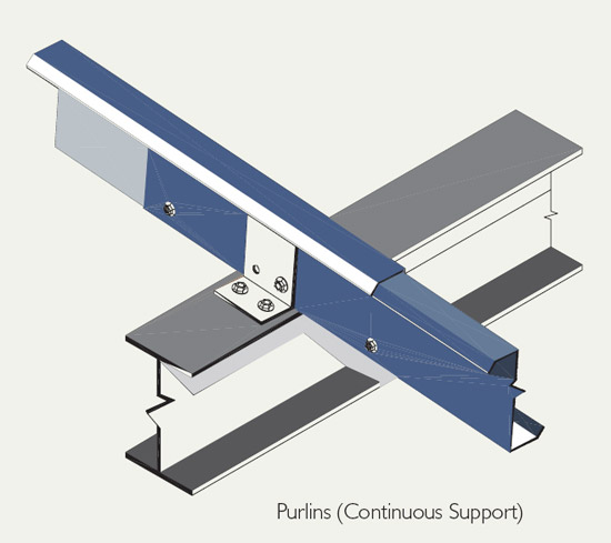
Roof purlins are cold-formed Z profiles, normally 200 to 250 mm deep out of 1.6 to 3.15 mm thick steel. These are fixed to the top flanges of the rafters by means of clips bolted to the rafters, and the purlin web bolted to the clips. Purlin ends overlap to act as continuous beams.
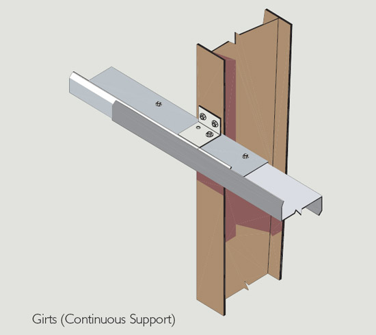
Wall girts are cold-formed Z sections, normally 200 to 250 mm deep out of 1.6 to 3.15 mm
thick steel. These are fixed to the outer flange of the side wall columns. There are two types of fixations:
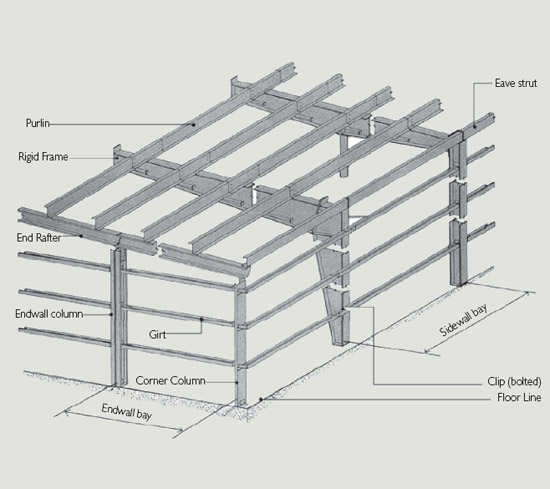
Eave struts are C profiles or double Z profiles, normally 200 to 250 mm deep out of 2 to 3.15 mm thick steel. These are fixed to the outer flange of the side wall columns by means of clips bolted to the column and eave strut bottom flange bolted to the clip. Roof purlins also act as wind struts and enable transfer of strut load to the side wall columns through adequate
bracing.
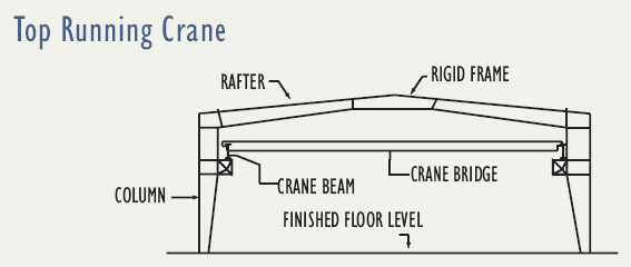
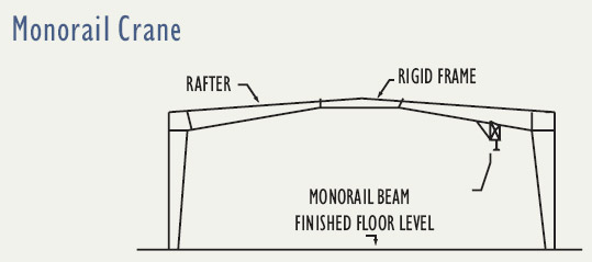
Interarch pre-engineered buildings can be designed to accept most types of crane systems such as EOT, Monorail, Under-hung cranes and other load carrying devices like conveyors etc., in both clear-span and multi-span buildings. When a crane system is to be integrated, Interarch's scope is limited to brackets and crane runway beams which support the crane system. Complete information on the crane system is required in order to design and estimate buildings with cranes.
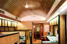
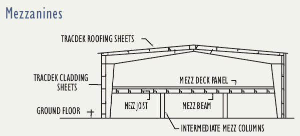
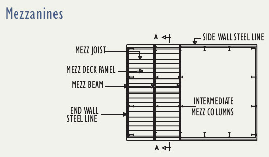
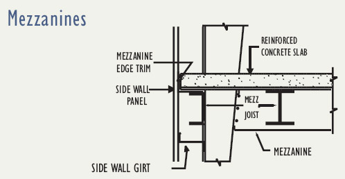
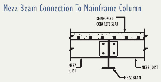
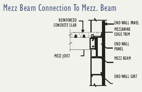
Intermediate mezzanine floors are possible in metal buildings. Mezzanine floors can be provided in complete or partial area in pre-engineered buildings to suit loading requirements for office and storage. Mezzanine floors consist of steel decks, supported by joists framed to the mezzanine beams. Main mezzanine beams normally run across the width of the building and are located under the main rafters while joists run parallel to the length of the building. The top flange of the joists fit immediately below the top flange of the mezzanine beam.
The economy of the mezzanine floor is affected by the applied load and support column spacings. Multi-level equipment platforms, catwalks, staircases etc. can be accommodated, if complete data is available.
Interarch metal buildings have the flexibility to allow integration of all kinds of standard bought out accessories. Interarch also supplies proprietary accessories.